Spark Erosion Process: A New Spark in Dentistry..
Department of Conservative & Endodontics, Srinivas Institue of Dental Sciences Surathkal, Mangalore, India, Department of Prosthodontics, Srinivas Institue of Dental Sciences Surathkal, Mangalore, India, Department of Prosthodontics, K.D Dental College & Hospital, Mathura, (U.P), India
INTRODUCTION
The dental profession is currently experiencing a technology explosion. Computerized instrumentation for periodontal diagnosis, patient charting, occlusal analysis, laboratory fabrication of restorations, and pre-treatment imaging for orthognathic surgical patients are examples of products currently available. Many of these devices represent the transfer of industrial technology to dental purposes.
Electrical discharge machining (EDM, also known as spark erosion) is one such procedure that has been used by the tool and die industry for nearly 50 years.
Spark erosion process is a modern precision laboratory procedures by which, a metal is precisely contoured into a desired shape by erosion by using accurately controlled electric discharge through two conductive objects immersed in a liquid medium. Basically there are two types of EDM –wire and probe type, of which the latter can be effectively used in dentistry.
HISTORY
- The idea for EDM came from man watching lightning—nature’s form of EDM.
- In the late 1700s, Sir Joseph Priestly discovered this phenomenon while observing the erosive effect of electric current on metal conductors.
- Shortly after World War II, the Lazerenko brothers of Russia announced their first electronic erosion machine, and since then, it has been used in various industries, especially aerospace, medical and micro engineering.
- The advent of computer-aided EDM in the early seventies helped it gain significance in manufacturing processes.
- In 1982, it was introduced into dentistry by Rubeling to fabricate precision attachments.
- Later, in the same year, Windeler received a patent for improving the fit of cast restorations using EDM and since 1990 it has been used widely in implant prostheses.
SCOPE IN DENTISTRY
Passive fit is the simultaneous and circumferential contact between components of prosthesis. It is imperative to limit stresses induced by prosthesis within physiologic limits. This implies that the fit of the prosthesis should be such that, the tooth or bone should be able to adapt or remodel to the stimuli. It is mainly applicable in implant prostheses where there is a lack of resiliency at the bone - implant interface.
A non-passive fit transmits undue tensile, compressive and shear stresses to the implant and bone. This is detrimental to long-term maintenance of osseo-integration and can cause crestal bone loss with possibility of screw loosening, pain, soft tissue irritation, implant fracture and prostheses fracture. Therefore, passive fit ideally in the range of 10μm is essential for preventing biologic and technical failures of implants and fixed partial dentures.
This can be easily achieved by the spark erosion process. Spark erosion can achieve passive fit of metal sub/super structures and porcelain veneered frameworks which are to be placed on implant abutments and at the metal coping-tooth interface in fixed partial restorations.
Precision attachments, friction pins, titanium copings for Procera All-Titan system and telescopic crowns can also be fabricated with this technology. Spark erosion surface treatment for better metalresin bonding is another important application being investigated.
ADVANTAGES OF SPARK EROSION
- Passive fit of restorations is achieved.
- Complex 3-dimensional structures can be shaped regardless of metal hardness since it is a thermal process.
- An extremely thin work piece can be machined without distortion as no mechanical forces are created.
- There is decreased stress on the work piece due to the cooling action of the di-electric fluid.
- Smooth finish of final restoration is ensured.
- There is decreased oxidation of metals during the procedure (especially useful in titanium to porcelain bonding).
- It is rapid, efficient and accurate (within 0.0254 mm).
- Frameworks with porcelain can be spark eroded without any stress on the porcelain due to the cooling action of the di-electric fluid.
DISADVANTAGES OF SPARK EROSION
- Eroding tends to affect the corrosion resistance of titanium.
- Skilled personnel and specialized lab equipment is mandatory.
- The high cost of the technique limits its usage.
MECHANICS OF SPARK EROSION
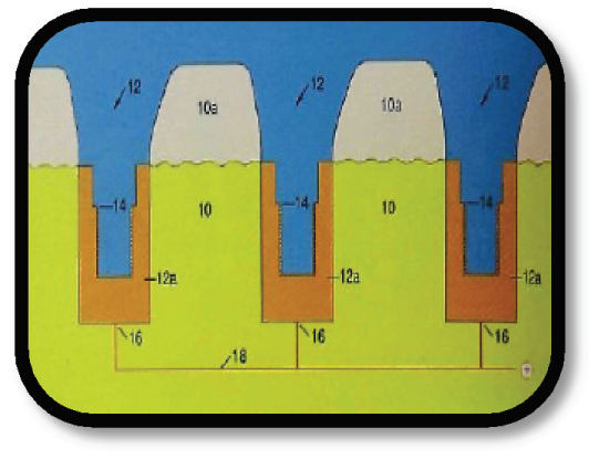
In a spark erosion machining unit, an electrode to work piece relationship is maintained in a liquid medium (di-electric fluid). The electrode (anode or positive potential) is usually made of graphite, copper, tungsten or zinc and is shaped into the negative form of the desired shape by CAD/CAM or milling. The work piece (negative potential or cathode) is the metal which is to be shaped into the desired form. The di-electric fluid functions as a conductor and coolant during the procedure. This whole unit has a power source that maintains a direct current. The power level selection is dictated by alloy properties used, size of object and amount of erosion required.

The exact nature of the EDM process is not known, A thermoelectric model has been proposed to explain how heat and electricity can act together to remove metal particles efficiently and with great precision.
- A space is maintained between the electrode and work piece throughout the machining process which is known as the cutting gap. The electrode moves towards and away from the work piece assisted by a hydraulic ram connected to it during the process.
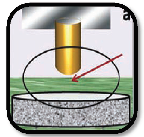
- As the voltage increases, the hydraulic ram brings the electrode nearer to the work piece. The electric field is strongest at the closest point between the electrode and the work piece i.e. electric field is directly proportional to the cutting gap.

- With increasing voltage, the di-electric fluid breaks down into ionized particles and an ionization channel is established.
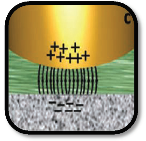
- When sufficient ionized particles have accumulated to overcome the insulating effect of di-electric fluid, a current is established. With increasing current, an electric discharge channel is formed.
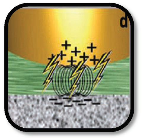
- The subsequent build-up of heat results in a vapour cloud formation which gradually expands.
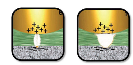
- Meanwhile, the voltage at the cutting gap is monitored with a reference voltage within the power supply. When voltage at the cutting gap exceeds the reference voltage, the power gets cut off. This drastically reduces the temperature at the cutting gap, triggering a collapse of the vapor bubble and generates a high-energy spark of temperature ranging from 8000- 12,000oC.
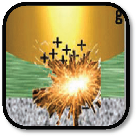
- The sudden energy produced causes vaporization of the work piece. The eroded particles are flushed away by introduction of fresh dielectric fluid.
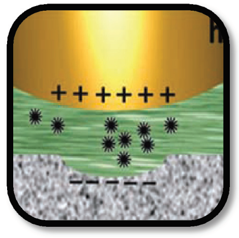
- When the voltage at the cutting gap falls below the reference voltage at the power source, the cycle repeats itself as the power source is activated automatically. These electric discharges occur at regular intervals and such cycles takes place about 250,000 times a second.
PROCEDURE FOR ACHIEVING PASSIVE FIT OF IMPLANT SUPER STRUCTURES
Günter Rübeling introduced the SAE Secotec Spark Erosion technique to implant dentistry in the early nineties. Frameworks which produce passive fit on implants can be fabricated with considerable ease.
- The spark erosion system consists of implant analogue shell, implant analogues (depending on the implant system used), copper implant electrodes that are identical to the implants used, plastic cylinders for waxing, insertion screws, torque wrench and short and long screws for the laboratory phase.
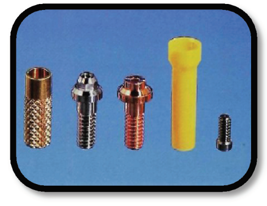
- The clinical analogs are not used for spark erosion process because of the following reasons:
»» The alloy properties of the analogs do not allow a clean and efficient machining of the workpieces.
»» The spark-erosion process alters the shape of the implant analogs and they do not maintain the form of the clinical abutments during the erosion process.
Thus they must be exchanged for copper electrodes before the erosion begins.
- Impressions are made after the second healing stage.
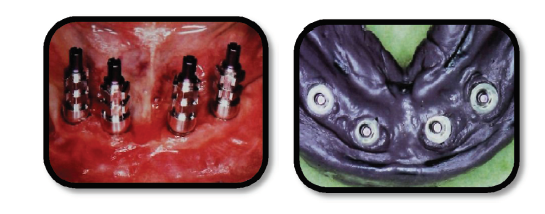
- Implant body analogues are screwed into implant analogue shells and secured to the impressions.
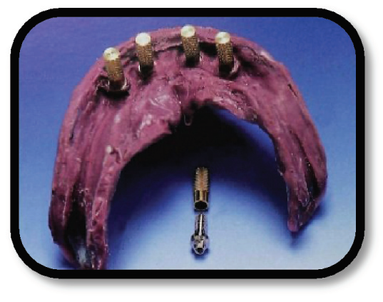
- Shells are connected with a copper braid to ensure conductivity during the process and Class 5 plaster was used for a partial pour beforehand, leaving the shell models entirely exposed.
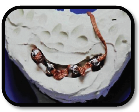
- The shell models are connected with low melting (65OC) alloy Melotteto form a single block. This eliminates plaster reactions induced by temperature and humidity, which could influence the position of the implant replicas.
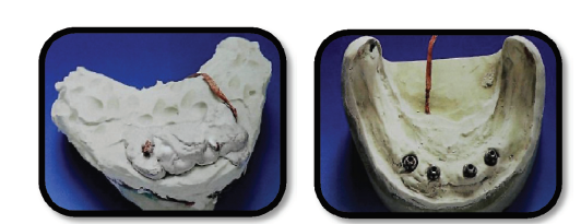
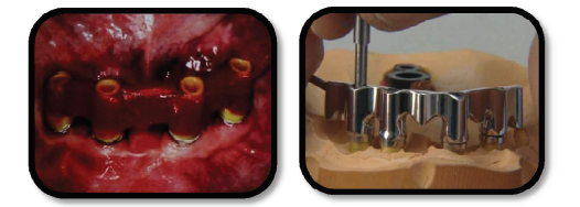
- Conventional procedures are followed till casting and finishing of the sub-structure is completed and Sheffield tests are carried out beforemachining to determine passivity. In order to perform this test, themetal sub-structure should be inserted over the supporting implants or abutments. Then the most distal retaining screw should be tightenedand the rest of the retaining screws should be kept out. If a gapappears between the remaining supporting implants or abutments and the metal sub-structure, it indicates that the metal framework does not fit passively.
- The cast with the implant analogues is placed horizontally in the spark erosion unit. The cradle of the machine which can be moved in all planes is then aligned over the cast and is attached to the cast bar (the workpiece), is with pattern resin. The cradle moves the bar towards and away from the electrodes during machining. The framework and the cast are connected to the power source by a copper braid.
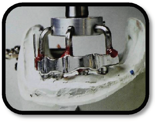
- The hydraulic ram lifts the framework from the model. Copper electrodes, identical to the implant analogues are used to replace them. The torque setting for the wrench used to screw the copper electrodes should be the same as that used for tightening the implant analogues into the implant analogue sleeves. This avoids discrepancy in height or fit.

- The di-electric fluid is introduced after the cutting gap is set in the unit. Then, the cradle moves the sub-structure onto the copper electrode and the erosion process is initiated.
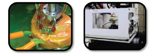
- The electrodes erode rapidly and need to be replaced during the process. Every time an electrode is changed, the power level should be reduced before initiating subsequent machining.
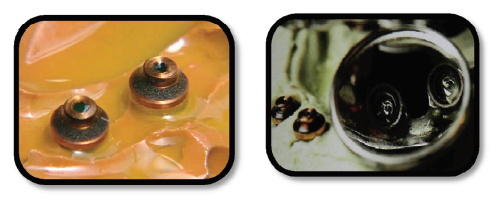
- The finished sub structure will exhibit a passive fit. The Sheffield test, when executed after machining, shows no gap between the metal

sub-structure and abutments, thus pointing to a passive fit at the abutment–framework interface.
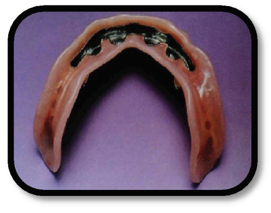
- A super-structure secured with custom latch receptacles is then fabricated over the metal sub-structure.
CROWN FABRICATION
- The Nobelpharma Company introduced a technique for fabricating veneered complete crowns using titanium and a compatible dental porcelain.
- The advantages claimed for this restoration are:
»» The soft tissue compatibility of titanium,
»» The low cost of titanium relative to noble metal casting alloys
»» The standardized procedures for fabricating the titanium coping.
- Solid cylindrical blanks of commercially pure titanium serve as the basis for developing the metal substructure of the restoration. The external surface of the titanium coping is created using a mechanical milling process and the internal configuration is formed by electrical discharge machining. Solid cylindrical blanks of graphite are used to form the electrodes.
- The clinical procedure for fabricating a Procera crown is the same. No special impression or die materials are required. Laboratory fabrication uses a tool system that enables the die, graphite blank, and titanium blank to be very precisely repositioned in the mechanical milling and EDM machines. The inner and outer surfaces of the titanium coping
- can be produced by different machines because of the accuracy of the positioning tool system.
- A duplicate of the master die is made using a hard die stone or epoxy resin die material. A 0.5-mm thick wax coping with the desired emergence profile and cervical collar width is then developed on the master die.
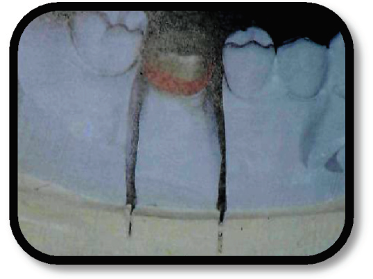
- The duplicate die is placed in a profile projector where it is centred and mounted in a special tool.
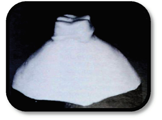
- A second function of the profile projector is to determine the size of the graphite and titanium blanks necessary for a given tooth preparation.
- The tool with the duplicate die is placed in a copy milling machine and three graphite replicas of the die are fabricated.
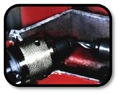
- An additional die replica is made using ureoleum, a rubberized stone material. Approximately 4 minutes are required to mill each die replica. The four die replicas and an appropriately sized titanium cylinder are individually mounted in a tool.
- The wax coping is removed from the master die and cemented on the mounted ureoleum die replica using cyanoacrylate glue; then the margins are readapted. This and a titanium cylinder are placed in a second copy milling machine to develop the external contour for the metal framework of the crown. It requires 5 or 6 minutes to mill the external surface.
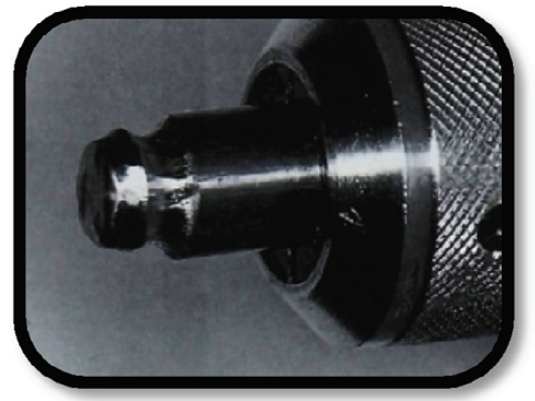
- Upon completion of the milling process, the milled titanium cylinder is inserted into another tool containing molten Melotte’s metal until the margin is completely covered.
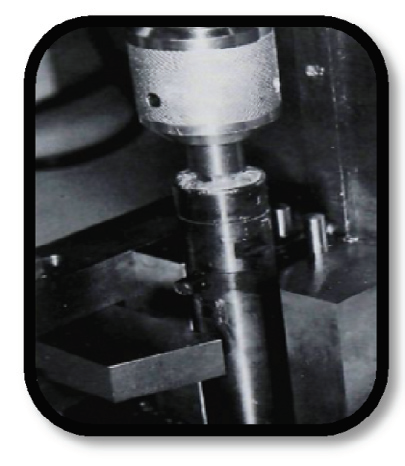
- After the Melotte’s metal has cooled, the unmilled portion of the titanium cylinder is cut off just below the longest margin.

- Tools containing a graphite die replica and the detached milled titanium blank in Melotte’s metal are placed in the EDM apparatus.
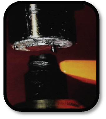
- It requires 8 to 10 minutes to electrical discharge machine the internal contour of the metal coping into the titanium. Three graphite electrodes are necessary because of the amount of electrode wear relative to metal removal. The metal coping and tool are placed in an oven to release the coping from the Melotte’s metal.
- The margin is then manually trimmed to fit the master die with a low-speed handpiece, using either carbide burs or ceramic stones. The internal surface of the coping is air abraded using 120μm of aluminous oxide to remove the oxide that has accumulated during the EDM process. The external surface of the coping to be veneered with porcelain is also air abraded using 120μm of aluminous oxide.
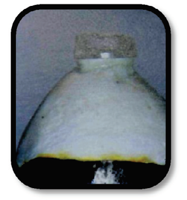
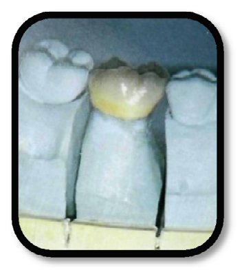
- Porcelain build-up and finishing procedures are accomplished in the usual manner. There are no restrictions regarding the type of luting agent that can be used for cementation of the restoration.
SUMMARY
An overview of the mechanism of action and applications of the spark erosion process in dentistry is presented. Such advances in dental technology help attain a passive fit of implant prostheses and fixed partial restorations, which is imperative in avoiding failures.
The cutting-edge accuracy thus achieved, helps perfect critical adjustments in individual components and the fabrication process, thereby increasing the quality of treatment and hence, patient contentment and clinical success.
Disclaimer from Guident
The views and opinions expressed in articles published in Guident are solely those of the authors and do not necessarily reflect the views of the editors, the editorial board or the publisher, Ivory India. Guident does not endorse any product, technique or treatment described. Clinical content is intended for qualified dental and medical professionals and is not a substitute for individual clinical judgement. Guident, its editors and the publisher accept no liability for any consequence arising from the use of information published in the journal.
How to cite this article
Dr. Lavanya Verma, Dr. Manoj Verma, Dr. Prateek Agrawal. Spark Erosion Process: A New Spark in Dentistry. Guident. 2013 May;6(7). Available from: https://guident.in/articles/prosthodontics/spark-erosion-process-a-new-spark-in-dentistry.html