
O-Ring Attachement System: Revisited
Mathura, India
OVER DENTURE ATTACHMENTS
- An overdenture attachment permits movement during function and removal from the mouth. As a result, all overdenture attachments wear and become less retentive.
- The portion of the attachment in the prosthesis should be designed to wear and be replaced, not the portion connected to the superstructure or implant.
- Ideally, the attachment should offer the possibility of controlling the degree of retention.
- A loose attachment used at initial delivery ensures prosthesis movement and decreases screw loosening during the first few months.
- A gradual increase in retentive capability may be achieved later by replacing the component within the encapsulator by a more retentive one. Likewise, if more retention is required in the future, a stiffer element, which is held by the same encapsulator, easily solves the problem.
INTRODUCTION
- The O-ring is perhaps the most popular stud attachment available to the dental profession to increase the retention of implant complete and partial overdentures as well as conventional overdentures.
- Compressive loading of implant O-ring attachments or attachment assemblies must occur only in conjunction with tissue loading; otherwise, forces may develop that can be destructive to the implant, the abutment, the tissue, and the prosthesis.
- When fabricating implant overdentures, it must always be remembered that, by definition, an overdenture is partially tissue supported (an exception is a completely implant-retained overdenture with multiple, bilateral abutments).

Fig.1 O-Ring Attachment
DESIGN
- O-rings are doughnut-shaped, synthetic polymer gaskets that possess the ability to bend with resistance and then return to their approximate original shape.

Fig. 2 Synthetic Polymer Gaskets – O Rings
- O-rings are elastomeric retentive attachments, usually made of silicone and shaped like the inner tube of a tire. They are held within metallic retaining rings with undercut grooves.
- The retaining rings are embedded within the denture base resin during the laboratory processing procedure or chairside with autopolymerizing resin.

Fig.3 Retentive Rings of O-Ring Attachment
- O-ring attaches to a post with a groove or undercut area for the O-ring.
- The O-ring has been used primarily in removable prosthetics as a retentive device. The O-ring has seen a resurgence in popularity with overdentures supported by endosteal implants and is widely available in a variety of implant systems.

Fig.4 Parts of O-Ring Attachment System
- The O-ring originally was made of natural rubber. The latex was heat treated with sulfur (vulcanization) to improve its properties.
- The resultant polymer, known as polyisoprene, still is used in the industry today.
ADVANTAGES:
- Ease in changing the attachment
- The wide range of movement
- Low cost,
- Different degrees of retention,
- Possible elimination of the time
- Less Cost of super structure for the prosthesis.
O-RING VERSUS PROSTHESIS MOVEMENT
- An O-ring is compressed radially between two mating surfaces consisting of a post and a metal encapsulator into which the O-ring is installed.
- All O-ring applications are categorized in terms of relative motion. In situations that require few or no moving parts or movement, the O-ring is classified as static (e.g., gasket or washer).

Fig. 5 Different types of Gaskets
- In situations involving reciprocation, rotation, or oscillating motion relative to the O-ring, it is classified as dynamic.
- The dynamic movement of the O-ring allows one of the most resilient or mobile types of attachments.
- O-rings may allow motion in six different directions.
- Two O-rings placed on a bar perpendicular to the midline may have two or three directions of prosthesis movement, depending on the resilient depression of the O-rings, whether a spacer is over the post head, and space is over the bar.
PARTS OF O-RING

-
- Metal Encapsulator
- A metal or plastic encapsulator permits the easy replacement of the O-ring after wearing or damage.
- This eliminates the need for chairside cold curing of a new attachment in place.
- Virtually every O-ring encapsulator has an undercut region that houses the O-ring, called the internal cavity.
- The O-ring volume must be larger than the internal cavity. As a result, the O-ring is compressed into position in the encapsulator and prevents the ring from moving or rolling while in place, which prematurely damages and wears the ring.
- The overall size of the encapsulator is larger than the O-ring and should be placed on the O-ring post during fabrication of the prosthesis to ensure adequate room is present for the volume of the restoration.

Fig.6 O-Ring attachment with and without metal encapsulator
- In general, the use of soft metals such as aluminum, brass, bronze, or gold should be avoided for the metal encapsulator.
- Stainless steel is recommended because it prevents damage to the encapsulator.
- Rounding of all corners of the encapsulator is recommended to prevent cutting or nicking of the O-ring during insertion or operation.
2.O-Ring Post
- The O-ring post usually is made of machined titanium alloy when used as an independent attachment or a delrim post that is waxed and cast in precious metal along with the connecting superstructure bar joining root forms.
- The post has:
- Head
- Neck
- Body
- The head is wider than the neck, and the O-ring is compressed over the head during insertion.
- Under the head the post has an undercut region called the neck or groove, which the ring engages after it stretches over the head.
- The body of the post is connected to the implant abutment or superstructure bar.
- The O-ring needs 5 mm or more height, the greatest of any attachments for overdentures.
- In addition, a space of 1 to 2 mm above the O-ring post is suggested to ensure that the ring seats completely over the head of the post.
- This space also prevents the post from penetrating or fracturing the restoration over the head and allows movement for a removable prosthesis type 5 (RP-5).
- This presents several disadvantages. A decreased crown height space may require a lower profile attachment.
- A denture tooth, O-ring, post, bar, and hygiene clearance often require at least 15 mm of crown height space to allow sufficient room for the acrylic base of the restoration to resist fracture.
- In addition, the higher the freedom of movement of a stress-relief attachment (required for all partial soft tissue–supported prostheses), the greater the moment of force on the attachment. Because the rotation point of O-rings is at the neck of the O-ring post, the point of rotation is not as high as first perceived
- However, if the prosthesis is made incorrectly and places lateral forces on the post, the lever arm of the post height can increase the force to the bar, screws, implants, and bone dramatically.
O-RING SIZE
- O-rings and posts may come in a variety of diameters depending on the space available within the volume of the prosthesis.

Fig.7 Different sizes of O-Ring attachment System
- The larger the diameter of the O-ring system, the easier it is to place the O-ring within the encapsulator.
- Troubleshooting complications is easier. Greater retention is possible. Typically three sizes of O-rings are used in implant prostheses.
- The inside surface of the O-ring rides against the post neck or groove. The internal diameter (hole diameter) of the O-ring must be smaller than the post neck and fit snugly in the groove diameter. The O-ring inside diameter will be stretched to 1% to 2% (not to exceed 5%) when in place against the post neck. If not, the O-ring will roll or wobble and increase wear and tear of the attachment.
- Overpolishing of a cast post neck region may unwittingly cause this complication.
O-RING HARDNESS
- O-ring hardness is measured with a durometer, which measures surface resistance to the penetration of an indentation point. The resultant numerical rating of hardness ranges from 0 to 100 in a Shore A Scale.
- The softest O-rings are usually 30 to 40, and the hardest are 80 to 90. Color is not indicative of hardness. In fact, most O-rings are black.
- Sometimes, however, for production coding or cosmetic reasons, nonstandard colors are desired.

Fig.8 Colour Coding in O-Ring
- Replacement of carbon black with tinted fillers (i.e., clay, calcium carbonate, or silicates) may result in undesirable alteration of working and physical properties. Increased wear and complication rates result.
O-RING MATERIALS
- The materials are available from a variety of industrial manufacturers
- The elastomeric materials meeting these requirements include
- Nitrile
- Silicone
- Fluorocarbon
- Ethylene propylene
Silicone is composed of a group of elastomers, made from silicone, oxygen, hydrogen, and carbon.
Silicones are known for their:
- Low-compression set characteristics
- Retention of flexibility
- Fungus resistant
- Odorless
- Tasteless
- Nontoxic.
DISADVANTAGES
- Poor tensile and tear strength,
- Low abrasion resistance,
- High friction characteristics
- In addition, silicone is not compatible with petroleum-based products such as petroleum jelly.
- Ethylene-propylene is a copolymer of ethylene and propylene, sometimes combined with a third co-monomer.
- Like silicone, this elastomer performs poorly when exposed to petroleum-based products.
- Nitrile is one of the more widely used elastomers for implant O-ring use. Nitrile combines excellent resistance to petroleum-based products, silicone greases, water, and alcohols, with a good balance of desirable properties such as high tensile strength and high abrasion resistance.
- Fluorocarbon also combines excellent resistance to petroleum products with outstanding chemical resistance. Fluorocarbon based compounds approach the ideal for a universal O-ring material
- Surface treatment of O-rings with lubricants helps protect them from abrasion, pinching, or cutting during performance.
- External lubrication also helps seat the O-rings easily into the metal encapsulator, with minimal twisting or damage and maximal assembly speed.
- In all cases requiring O-ring lubrication, a lubricant should be selected that is compatible with the O-ring compound and the oral environment.
- Nitrile O-rings may be lubricated with petroleum jelly or petroleum-based ointments. Petroleum-based products will damage silicone O-rings, and therefore a water-based lubricant (e.g., KY-Jelly [ Johnson& Johnson], which has a glycerine component) should be used.
TROUBLESHOOTING
- O-rings typically fail in their application because of the combined adverse effects of stress and environmental elements (i.e., friction, heat, and swelling).
- Such environmental factors may be compounded by incorrect O-ring size, improper laboratory technique, installation damage during final component assembly, and failure to maintain or lubricate the O-ring properly.
Extrusion and Nibbling
- Extrusion and nibbling occur with forced extension of part of the O-ring into the clearance gap of the metal encapsulator.
- The problem is identified by O-ring diameter enlargement or many small bites (nibbles) taken from the internal diameter of the O-ring, caused when O-ring materials are too soft, oral fluids degrade the O-ring, or the O-ring is too large for the metal encapsulator.
- The solution is to use a harder O-ring material or install a properly sized O-ring.
2.Spiral Failure
- Spiral failure is caused when certain segments of the O-ring slide while other segments simultaneously roll.
- At a single point on its periphery, the O-ring gets caught on an eccentric component or against the metal encapsulator wall, causing twisting, spiraling, or surface cuts. Problem sources include an uneven surface or finish of the post by the laboratory, inadequate lubrication, or excessive O-ring material softness.
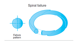
- The suggested solution(s) are evaluation of the post to ensure that it is not out of round, increasing O-ring hardness, and making sure the patient uses a lubricant daily.
Spiral failure of an O-ring results when one portion of the gasket does not slide during insertion or function. This failure is more common in custom-cast post heads or when to soft an O-ring is used. The surface of the O-ring exhibits a series of deep spiral patterns.
3. Abrasion
Abrasion may occur in dynamic O-rings involved in reciprocating, oscillating, or rotary motion. This failure pattern can be identified by a flattened, worn surface on the inner diameter of a cross section of the O-ring. The most common cause is bruxism by the patient or lifting and seating of the overdenture as a nervous habit.
Another source of the problem includes a rough metal surface (acting as an abrasive). The suggested solutions are to use the recommended metal finishes, change to a more abrasionresistant O-ring material, or eliminate abrasive contamination, which may be found in the diet (e.g., the abrasive particles found in chewing tobacco).
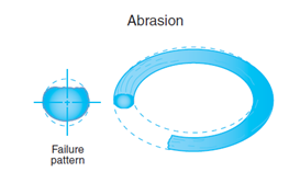
An abrasion on the O-ring occurs when the device wears, rather than slides into position.
Parafunctional habits such as bruxism or repeated lifting and seating of the restoration
are the most common causes. Abrasion occurs primarily in dynamic O-rings involving reciprocating oscillating or rotary motion and is identified by a flattened surface on one side. Daily lubrication of the ring decreases this complication.
4. Compression Set
- Compression set failure produces flat surfaces on both sides of the cross section of the O-ring.
- The most common cause for this type of failure is parafunctional clenching on the prosthesis. Other problem sources include selection of an elastomer with poor compression set properties or excessive “squeezing” or biting of the prosthesis into place to seat the restoration.
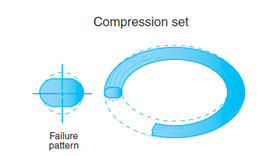
- The suggested solution is to make sure the prosthesis is removed at night or to reduce the O-ring hardness, which reduces the compression required to insert the prosthesis.
- Compression set failure of an O-ring results primarily from clenching on the prosthesis. Compression set failure produces flat surfacing on both sides. The restoration should be removed during sleeping to minimize this problem.
5. Installation Damage
- Installation damage is one of the most common types of complication. This failure mode is marked by short cuts, notches, or a skinned or peripherally peeled surface.
- The problem sources include sharp edges on the encapsulator from poor laboratory technique, sharp edges on the O-ring post head, too large an O-ring for the encapsulator, twisting or pinching of the O-ring into the encapsulator, too small an O-ring for the post, or lack of O-ring lubrication during installation.
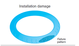
Installation damage is a common condition.
This failure mode is marked by short cuts, notches, and a skinnedor peripherally peeled surface. To reduce this problem, lubricationshould be used during placement.
CONCLUSION
- The O-ring is a stud attachment that can be used to increase the retention of implant complete and partial overdentures. O-rings possess a number of advantages, including ease of use and maintenance, low cost, and possible elimination of a superstructure bar.
- As O-rings wear over time, they gradually lose retention and must be replaced. O-ring abutments must be parallel to each other to prevent possible fracture at the neck and to prevent difficulty in insertion and removal of the prosthesis.
REFERENCES
- AN OVERVIEW OF THE O-RING IMPLANT OVERDENTURE ATTACHMENT: CLINICAL REPORTS Sheldon Winkler, DDS Jack Piermatti, DMD Amy Rothman, DMD, MA Georgios Siamos, DDS, MS. Journal of Oral Implantology 2002, 28;2: 82-86.
- Dental Implant Prosthetics. Carl E. Misch
Disclaimer from Guident
The views and opinions expressed in articles published in Guident are solely those of the authors and do not necessarily reflect the views of the editors, the editorial board or the publisher, Ivory India. Guident does not endorse any product, technique or treatment described. Clinical content is intended for qualified dental and medical professionals and is not a substitute for individual clinical judgement. Guident, its editors and the publisher accept no liability for any consequence arising from the use of information published in the journal.
How to cite this article
Dr. Manpreet Kaur Dr. Manesh Lahori Department of Prosthodontics K.D Dental College & Hospital. O-Ring Attachement System: Revisited. Guident. 2017 Oct;10(11). Available from: https://guident.in/articles/implantology/o-ring-attachement-system-revisited.html

